8 pages
4.1 Entities, relationships, and attributes
The entity-relationship model
Database design begins with verbal or written requirements for the database. Requirements are formalized as an entity-relationship model and then implemented in SQL.
An entity-relationship model is a high-level representation of data requirements, ignoring implementation details. An entity-relationship model guides implementation in a particular database system, such as MySQL.
An entity-relationship model includes three kinds of objects:
- An entity is a person, place, product, concept, or activity.
- A relationship is a statement about two entities.
- An attribute is a descriptive property of an entity.
The model only includes entities, relationships, and attributes that are relevant to the database.
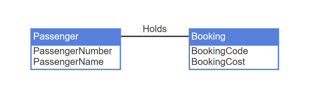
- In an airline reservation system, Passenger and Booking are entities.
- Holds is a relationship between Passenger and Booking.
- PassengerNumber, PassengerName, BookingCode, BookingCost are attributes.
Terminology
Attribute is used in both entity-relationship and relational models. In the relational model, attribute is a formal term for column. Since entity-relationship attributes typically become relational columns, the meaning of attribute is similar in both models.
Entity-relationship diagram and glossary
An entity-relationship diagram, commonly called an ER diagram, is a schematic picture of entities, relationships, and attributes. Entities are drawn as rectangles. Relationships are drawn as lines connecting rectangles. Attributes appear as additional text within an entity rectangle, under the entity name.
Entities and relationships always appear in ER diagrams. Attributes are optional and only appear when additional detail is needed.
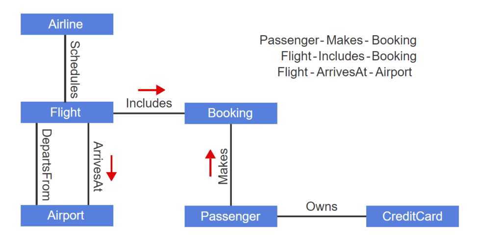
- The ER diagram for an airline reservation system has multiple entities and relationships but no attributes.
- Each entity-relationship-entity is read following the direction of the relationship verb.
- The verb “Includes” points to the right, and the verb “ArrivesAt” points down.
A glossary, also known as a data dictionary or repository, documents additional detail in text format. A glossary includes names, synonyms, and descriptions of entities, relationships, and attributes. For simple databases with few users, a database designer may record the glossary with a text editor. For more complex databases, the designer may use a database or software tool specifically designed for glossaries.
The ER diagram and glossary are complementary and, together, completely describe an entity-relationship model.
Types and instances
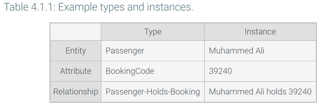
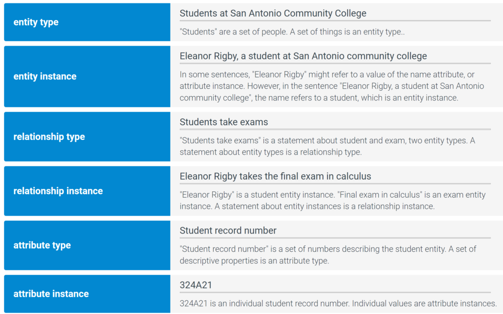
In entity-relationship modeling, a type is a set:
- An entity type is a set of things. Ex: All employees in a company.
- A relationship type is a statement about entity types. Ex: Employee-Manages-Department.
- An attribute type is a set of values. Ex: All employee salaries.
Entity, relationship, and attribute types usually become tables, foreign keys, and columns, respectively.
An instance is an element of a set:
- An entity instance is an individual thing. Ex: The employee Sam Snead.
- A relationship instance is a statement about entity instances. Ex: “Maria Rodriguez manages Sales.”
- An attribute instance is an individual value. Ex: The salary $35,000.
Entity, relationship, and attribute instances usually become rows, foreign key values, and column values, respectively
Database design
Complex databases are developed in three phases:
- Analysis develops an entity-relationship model, capturing data requirements while ignoring implementation details.
- Logical design converts the entity-relationship model into tables, columns, and keys for a particular database system.
- Physical design adds indexes and specifies how tables are organized on storage media.
Analysis is particularly important for complex databases with many users when documenting requirements is challenging. For small databases with just a few tables and users, analysis is less important and often omitted.
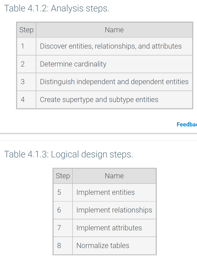
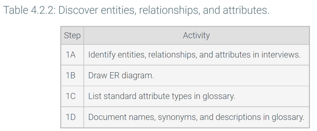
Analysis and logical design steps are summarized in the table below. Although these steps are presented in sequence, in practice execution is not always sequential. Often an early step is revisited after a later step is completed.
Physical design is dependent on specific index and table structures, which vary greatly across relational databases. Physical design is discussed elsewhere in this material.
4.2 Discovery
Discovery
Entities, relationships, and attributes are discovered in interviews with database users and managers. Users and managers are usually familiar with data requirements from an old database, or perhaps a manual process with paper records. When users are difficult to reach, a database designer may communicate with surrogates. Ex: A sales representative might communicate on behalf of prospective customers.
In addition to interviews, written documents are a good source of data requirements. Ex: The user manual for an older version of the database is a good source of requirements.
In interviews and documents, entities, relationships, and attributes surface as nouns and verbs:
- Entities usually appear as nouns, but not all nouns are entities. Designers should ignore nouns that denote specific data or are not relevant to the database.
- Relationships are often expressed as verbs. Designers should ignore statements that are not about entities, not relevant to the database, or redundant to other relationships. Designers should look for relationships that are not explicitly stated, since users may overlook important information.
- Attributes are usually nouns that denote specific data, such as names, dates, quantities, and monetary values.
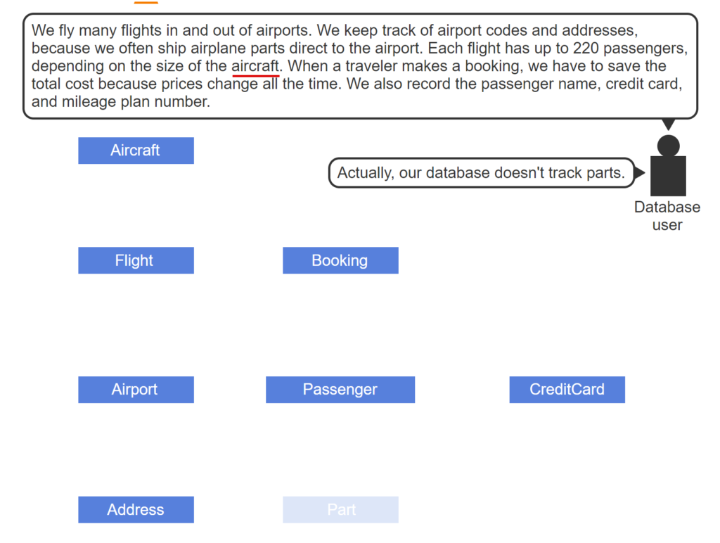
- In an interview with a database user, flight, airport, aircraft, passenger, and booking are entities.
- Airplane is another word for aircraft. Traveler is another word for passenger.
- Usually, address and credit card have many details and are entities.
- Further interviews determine the database does not track parts. Part is not an entity.
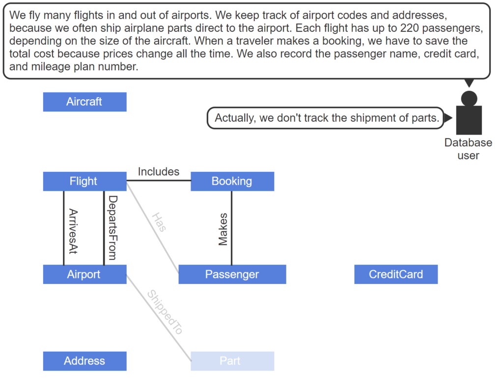
- Flight-ArrivesAt-Airport, Flight-DepartsFrom-Airport, and Passenger-Makes-Booking are relationships.
- Passenger can be determined from booking. Replace Flight-Has-Passenger with Flight-Includes-Booking.
- Further interviews determine the database does not track parts. Part-ShippedTo-Airport is not a relationship.
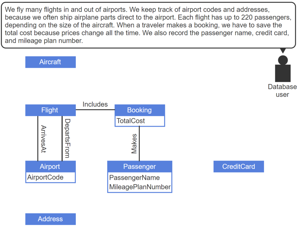
- Airport code, total cost, and name are attributes of Airport, Booking, and Passenger.
- Mileage plan number is an attribute of Passenger or, if additional mileage plan information is tracked, a separate entity.
Names
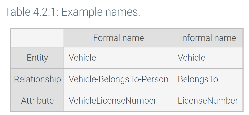
Entity names are a singular noun. Ex: Employee rather than Employees. The best names are commonly used and easily understood by database users.
Relationships names have the form Entity-Verb-Entity, such as Division-Contains-Department. When the related entities are obvious, in ER diagrams or informal conversation, Verb is sufficient and entity names can be omitted. The verb should be active rather than passive. Ex: Manages rather than IsManagedBy. Occasionally, the same verb relates different entity pairs. Ex: Order-Contains-LineItem and Division-Contains-Department.
Attribute names have the form EntityQualifierType, such as EmployeeFirstName:
Entityis the name of the entity that the attribute describes. When the entity is obvious, in ER diagrams or informal conversation,QualifierTypeis sufficient and the entity name can be omitted.Qualifierdescribes the meaning of the attribute. Ex: First, Last, and Alternate. Sometimes a qualifier is unnecessary and can be omitted. Ex: StudentNumber.Typeis chosen from a list of standard attribute types such as Name, Number, and Count. Attribute types are not identical to SQL data types. Ex: “Amount” might be an attribute type representing monetary values, implemented as the MONEY data type in SQL. “Count” might be an attribute type representing quantity, implemented as NUMBER in SQL.
Standard attribute types are documented in the glossary and applied uniformly to all attribute names.
Synonyms and descriptions
Often, entity, relationship, and attribute names have synonyms. Ex: Representative may be a synonym for SalesAgent. Synonyms are common in informal communications. To avoid confusion, one official name is selected for each entity, relationship, and attribute. Other names are documented in the glossary as synonyms.
The glossary also contains complete descriptions of entities, relationships, and attributes. The description states the meaning of each entity, relationship, or attribute in complete sentences. The description begins with the name and includes examples and counterexamples to illustrate usage.
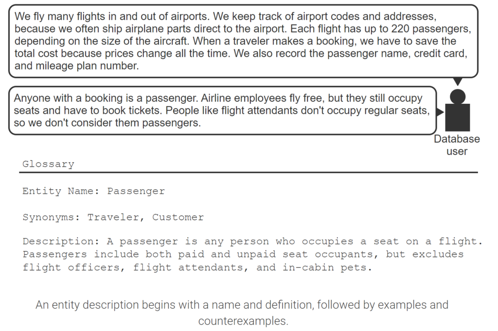
- Traveler is a synonym of passenger.
- An entity description begins with a name and definition, followed by examples and counterexamples.
Database design
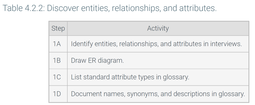
The first step of the analysis phase is discovery of entities, relationships, and attributes in interviews and document review. As discovery proceeds, the designer draws an ER diagram, determines standard attributed types, and documents names, synonyms, and descriptions in the glossary.
Although the step numbers suggest a sequence, database designers commonly move back and forth between steps. As names, synonyms, and descriptions are documented, additional entities, relationships, and attributes are discovered. The ER diagram and glossary are usually developed in parallel.
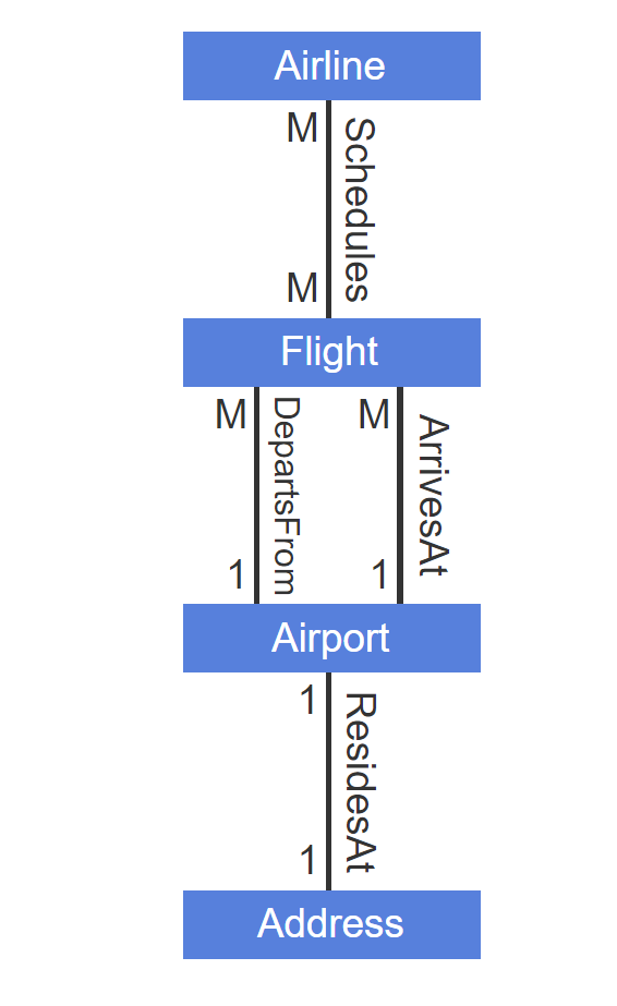
- Each flight departs from at most one airport.
- Each airport has many departing flights.
- ArrivesAt and DepartsFrom have the same maxima.
- Each airline schedules many flights. When multiple airlines share the same flights, each flight can be scheduled by many airlines.
- Each airport resides at at most one official address. Each address has at most one airport.
Relationship minimum
Relationship minimum is the least number of instances of one entity that can relate to a single instance of another entity. A relationship has two minima, one for each of the related entities. Minima are usually specified as zero or one. On ER diagrams, minima are shown after maxima in parentheses. Ex: M(1) or M(0).
Ex: For the Employee-WorksIn-Department relationship, a new department may have no employees, and each employee must be assigned to a department at all times. Thus, Employee-WorksIn-Department minima are zero-one.
Occasionally, relationship minimum is a number greater than one. Ex: Two forms of identification are required for customers, and each identification document belongs to only one customer. The Customer-Has-Identification minima are one-two.
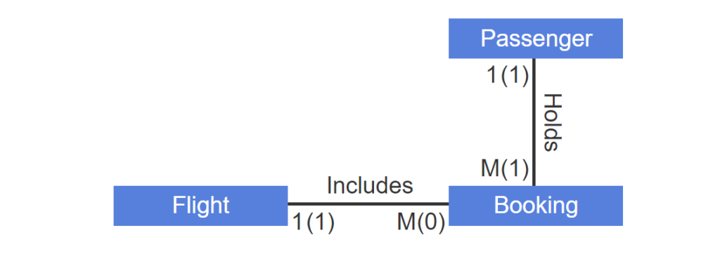
- Each booking must be included on exactly one flight and be held by at least one passenger.
- A new flight includes no bookings.
- The definition of passenger requires that all passengers hold a booking.
- Maxima and minima appear together on ER diagrams.
Attribute maximum
Entities have an implicit relationship with their attributes, called Entity-Has-Attribute. This relationship, like any other, has maxima and minima.
The following terms describe Entity-Has-Attribute maxima:
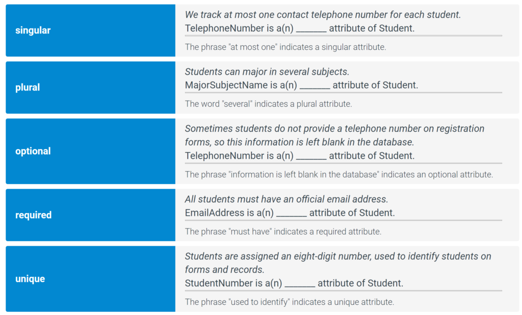
- Singular attribute — each entity instance has at most one attribute instance.
- Plural attribute — each entity instance can have many attribute instances.
- Unique attribute — each attribute instance describes at most one entity instance.
Unique attributes are not the same as singular attributes. Ex: FullName is singular, because each employee has one name. FullName is not unique, because each name can describe several employees.
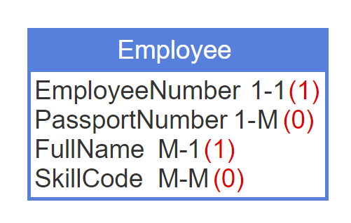
In ER diagrams, entity and attribute maxima appear as M or 1, separated by a dash and following the attribute name. Occasionally, attribute maxima are specified as a number greater than one. Ex: The ParentName attribute of the Person entity has maximum of two, since each person has at most two biological parents.
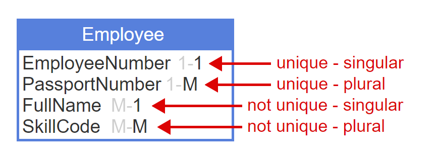
- Each number is assigned to one employee. Each employee has one number.
- PassportNumber is unique, since each passport belongs to one employee.
- PassportNumber is plural, since an employee can hold passports from different countries.
- A name can describe many employees. Each employee has one name.
- Each skill can describe many employees. Each employee can have many skills.
- ER diagrams sometimes omit the entity maximum.
Attribute minimum
The following terms describe Entity-Has-Attribute minima:
- Required attribute — each entity instance has at least one attribute instance.
- Optional attribute — each entity instance can have zero attribute instances.
The minimum on the Entity side of Entity-Has-Attribute is not important in database design and has no special terminology.
In ER diagrams, attribute minima appear as (0) or (1), after the maxima. Usually only attribute minimum is noted on diagrams, since entity minimum does not affect database design. Occasionally, attribute minima are specified as a number greater than one. Ex: If two forms of identification are required, the IDNumber attribute of the Person entity has a minimum of two.
Database design
Relationship and attribute cardinality depends on business rules. Ex: Usually Employee-WorksIn-Department maxima are one-many. If a company assigns employees to multiple departments, however, the maxima are many-many.
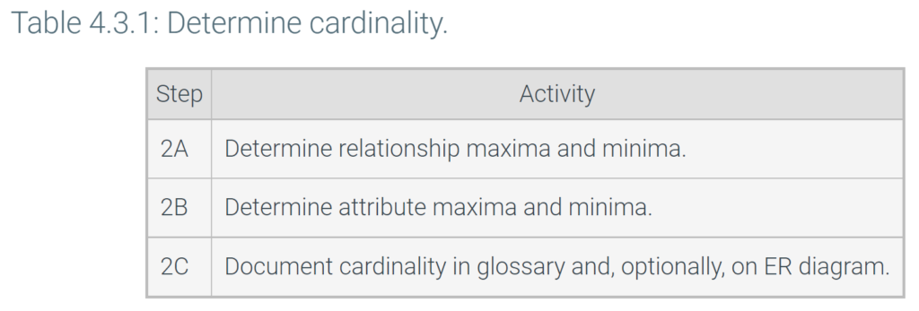
During the analysis phase, the designer looks for cardinality business rules in interviews and document review. The designer then converts business rules into 0, 1, and M specifications, and documents specifications in the ER diagram and glossary.
Depending on the desired level of detail, cardinality does not always appear on ER diagrams. Usually, ER diagrams are drawn with software tools that can automatically show or hide cardinality.
4.4 Independent and dependent entities
Independent and dependent entities
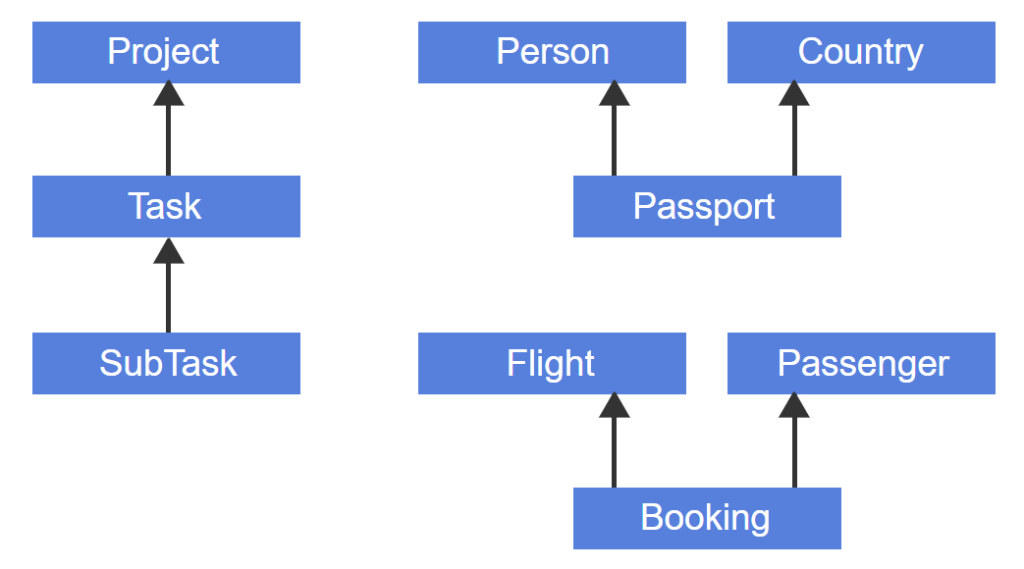
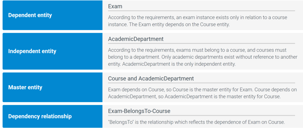
Entity A depends on entity B if instances of A exist only in relation to instances of B. Ex: Task depends on Project if all tasks must be part of a project. A project must exist before project tasks are created. When a project is deleted, all project tasks must also be deleted.
A dependent entity depends on another entity, called the master entity. The dependent and master entities are related by a dependency relationship. Ex: Task-BelongsTo-Project is a dependency relationship. On ER diagrams, the dependency relationship is drawn as an arrow pointing to the master entity.
An entity can depend on multiple master entities. Hierarchies of dependent entities are common.
An independent entity does not depend on any other entity. Ex: In a university database, students and departments can be created without reference to any other entity, so Student and Department are independent entities.
Terminology
Dependence and depend on have different meanings in entity-relationship and relational models. In the entity-relationship model, dependence means each instance of a dependent entity always relates to an instance of another entity. In the relational model, dependence means each value of a column relates to at most one value of another column. Formally, entity-relationship dependence is called existence dependence and relational dependence is called functional dependence.
ER model and diagram conventions
This material uses relatively simple conventions for ER models and diagrams. However, these conventions vary widely. Ex: Some ER models may:
- Allow relationships between three or more entities.
- Decompose a complex model into a group of related entities, called a subject area.
- Refer to independent entities as strong and dependent entities as weak.
Some ER diagrams may:
- Depict relationship names inside a diamond.
- Depict dependency relationships with a diamond rather than an arrowhead.
- Use color, dashed lines, or double lines to convey additional information.
Variations in diagram conventions for cardinality are common. One popular convention depicts cardinality as follows:
- Zero — a circle across the end of a relationship
- One — a bar across the end of a relationship
- Many — three lines, called crow’s feet, at the end of a relationship
Several model and diagram conventions are widely used, including:
- Unified Modeling Language, or UML, is commonly used for software development. Software data structures are similar to database structures, so UML includes ER conventions.
- IDEF1X stands for Information DEFinition version 1X. IDEF1X became popular, in part, due to early adoption by the United States Department of Defense.
- Chen notation appeared in an early ER modeling paper by Peter Chen. Chen notation is not standardized but often appears in literature and tools.
By and large, differences between conventions are stylistic rather than substantial. The choice of convention does not usually affect the resulting database design.
The animation below shows one subject area from the Cloud Information Model, an industry model for sales fulfillment databases. The Cloud Information Model illustrates common diagram conventions such as crow’s feet, subject areas, and diamond notation for dependency relationships.
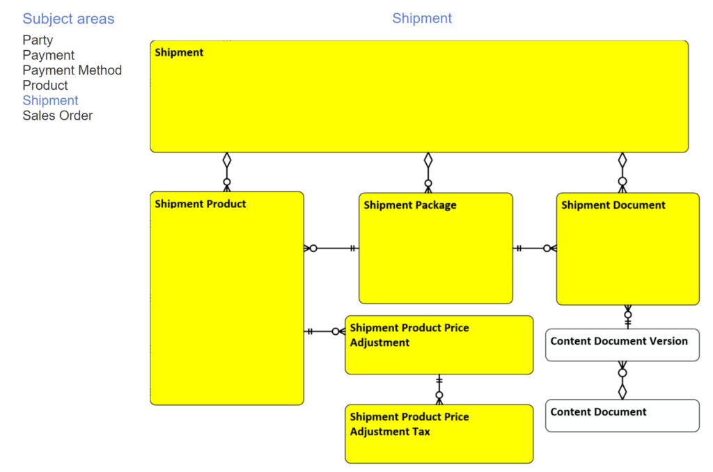
- The Cloud Information Model is a standard model for sales fulfillment. The model is divided into subject areas.
- The Shipment subject area contains entities related to product shipments. Entity rectangles have round corners.
- Cardinality is depicted with crow’s foot notation. Identifying relationships are depicted with diamonds.
- Entities inside the subject area are yellow. Related entities outside the subject area are white.
Database design
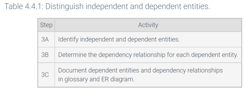
After entities, relationships, attributes, and cardinality are determined, the database designer distinguishes independent and dependent entities. For each dependent entity, the dependency relationship is identified and named. Dependent entities and dependency relationships are documented in the glossary and ER diagram.
Most database designers use software tools to manage ER diagrams. Software tools usually allow users to choose from alternative conventions and automatically switch between conventions.
4.5 Supertype and subtype entities
Supertype and subtype entities
An entity type is a set of entity instances. A subtype entity is a subset of another entity type, called the supertype entity. Ex: Managers are a subset of employees, so Manager is a subtype entity of the Employee supertype entity. On ER diagrams, subtype entities are drawn within the supertype.
A supertype entity usually has several subtypes. Attributes of the supertype apply to all subtypes. Attributes of a subtype do not apply to other subtypes or the supertype.
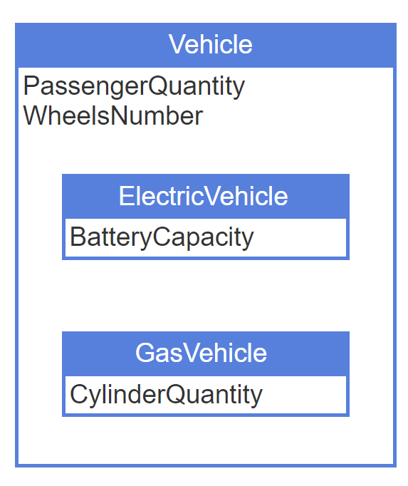
- Vehicle supertype has ElectricVehicle and GasVehicle subtypes.
- Number of passengers and number of wheels apply to both electric and gas vehicles.
- Battery capacity applies to electric vehicles only.
- Number of cylinders applies to gas vehicles only.
A subtype entity depends on its supertype. Ex: Manager depends on Employee. Before Steve becomes a manager, Steve must first become an employee. When Steve is no longer an employee, Steve cannot be a manager.
The dependency relationship from subtype to supertype is called an IsA relationship. Ex: Manager-IsAn-Employee. On ER diagrams, the IsA relationship is drawn as an arrow from the subtype to the supertype. Since a subtype entity always depends on its supertype, however, the IsA relationship is assumed and can be omitted from the ER diagram.
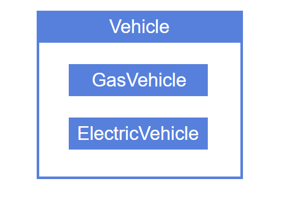
- Subtype entities have an IsA dependency relationship to the supertype.
- IsA relationships are assumed and usually not shown in an ER diagram.
Similar entities and optional attributes
Supertype and subtype entities are often created from similar entities and optional attributes.
Similar entities are entities that have many common attributes and relationships. Similar entities become subtypes of a new supertype entity, as in the animation below. Common attributes and relationships move to the new supertype entity. Attributes and relationships that are not shared remain with the subtype entities.
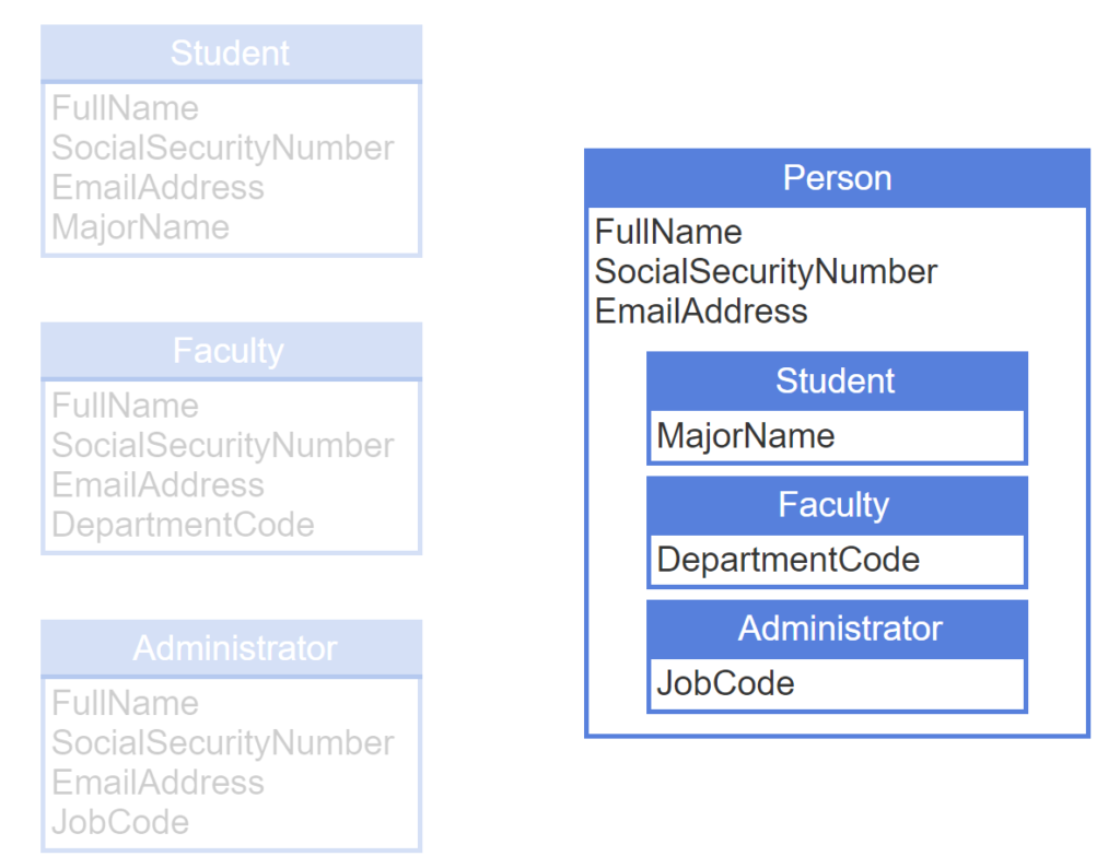
- Student, Faculty, and Administrator are similar entities with common attributes FullName, SocialSecurityNumber, and EmailAddress.
- Common attributes move to a new supertype entity called Person.
- Subtype-specific attributes remain attributes of each subtype.
An entity with many optional attributes also suggests new supertype and subtype entities. The entity becomes a supertype entity and retains all required attributes. Optional attributes become required attributes of new subtype entities.
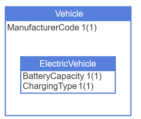
- Vehicle has required attribute ManufacturerCode and optional attributes BatteryCapacity and ChargingType.
- Optional attributes become required attributes of the new subtype entity ElectricVehicle.
Creating a new supertype for similar entities, or a new subtype for optional attributes, is neither an automatic nor objective decision. Similar entities with many common attributes are good candidates for a new supertype. Entities with many optional attributes are good candidates for a new subtype.
Partitions
A partition of a supertype entity is a group of mutually exclusive subtype entities. Subtype entities in a partition cannot share common instances. Ex: Undergraduate and graduate students are mutually exclusive subsets of students. UndergraduateStudent and GraduateStudent partition the supertype entity Student.
Each partition corresponds to a partition attribute of the supertype entity. The partition attribute indicates which subtype entity each instance belongs to. Ex: StatusCode is a partition attribute of the Student supertype entity. Code ‘U’ indicates the student is an undergraduate, and code ‘G’ indicates the student is a graduate.
A supertype entity can have zero, one, or many partitions.
Database design
After entities, relationships, attributes, cardinality, and independent and dependent entities are determined, the database designer looks for supertype and subtype entities. Similar entities and optional attributes suggest new supertype and subtype entities and warrant special attention. Mutually exclusive subtype entities are grouped into partitions. For each partition, a partition attribute is added to the supertype entity.
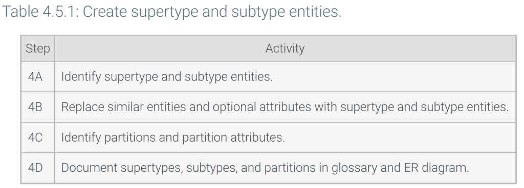
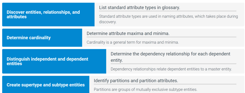
Creating supertype and subtype entities is the last of four analysis steps:
- Discover entities, relationships, and attributes
- Determine cardinality
- Distinguish independent and dependent entities
- Create supertype and subtype entities
Logical design follows analysis. Logical design converts an entity-relationship model to tables, columns, and keys for a specific database system.
4.6 Implementing entities
Selecting primary keys
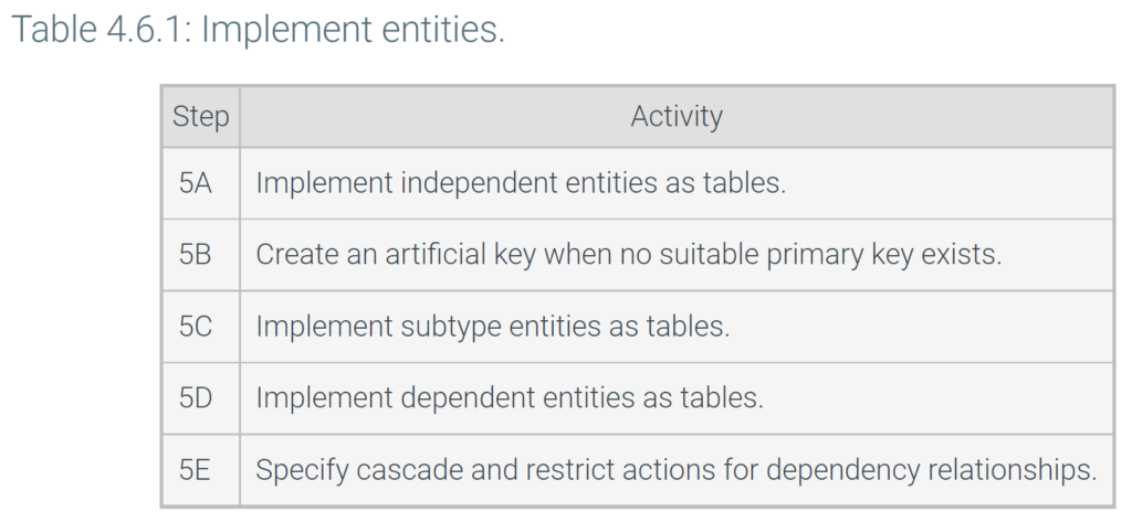
In the first step of the logical design phase, each entity becomes a table and each attribute becomes a column. Table and columns are reviewed and revised in subsequent logical design steps.
As tables and columns are specified, primary keys are selected. Primary keys must be unique and not NULL. A non-NULL column is equivalent to a required attribute, so primary keys correspond to unique and required attributes. In addition, primary keys should be:
- Stable. Primary key values should not change. Unstable primary keys cause database management problems. When a primary key value changes, statements that specify the old value must also change, and the new primary key value must cascade to foreign keys.
- Simple. Primary key values should be easy to type and store. Small values are easy to specify in an SQL WHERE clause and speed up query processing. Ex: A 2-byte integer is easier to type and faster to process than a 15-byte character string.
- Meaningless. Primary keys should not contain descriptive information. Descriptive information occasionally changes, so primary keys containing descriptive information are unstable.
On table diagrams, solid bullets denote attributes that become primary keys.
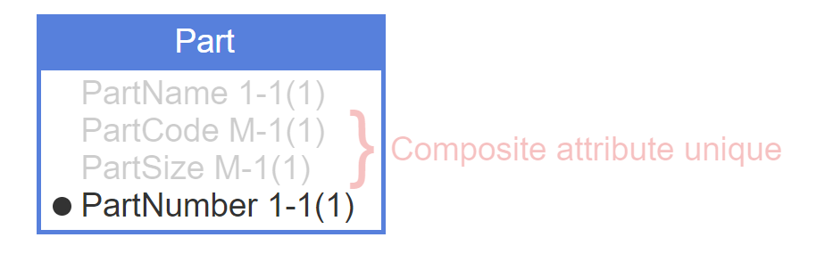
- PartName is unique and required, but also complex and meaningful. PartName is not a good primary key.
- PartCode and PartSize are not individually unique; however, the composite (PartCode, PartSize) is unique, as well as required and simple.
- PartSize is meaningful and might change due to data entry errors or part redesign. (PartCode, PartSize) is not a good primary key.
- The database designer creates a new PartNumber column for internal database use. PartNumber is unique, required, stable, simple, and meaningless, and therefore a good primary key.
Implementing independent entities
An independent entity becomes an independent table. The primary key must be unique and non-NULL, and should be stable, simple, and meaningless. Single-column primary keys are best, but if no such column exists, a composite primary key may have the required properties.
An artificial key is a single-column primary key created by the database designer when no suitable single-column or composite primary key exists. Usually artificial key values are integers, generated automatically by the database as new rows are inserted to the table. Artificial keys are stable, simple, and meaningless.
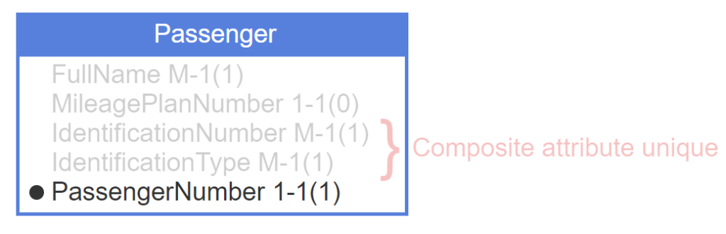
- Passenger is an independent table. Each attribute becomes a column in the initial design.
- FullName is not unique and cannot be the primary key.
- Not all passengers have a mileage plan number. MileagePlanNumber is not required and cannot be the primary key.
- Every passenger must provide identification, such as a driver’s license or passport. The composite (IdentificationNumber, IdentificationType) is unique.
- Passengers may provide different identification in the future, so (IdentificationNumber, IdentificationType) is unstable and a poor primary key.
- Since no suitable primary key exists, a database designer creates an artificial key PassengerNumber.
Implementing subtype entities
A subtype entity becomes a subtype table and is implemented as follows:
- The primary key is identical to the supertype primary key.
- The primary key is also a foreign key that references the supertype primary key.
The foreign key implements the ‘IsA’ dependency relationship. Foreign keys that implement dependency relationships usually have the following referential integrity actions:
- Cascade on primary key update and delete
- Restrict on foreign key insert and update
Referential integrity actions are described elsewhere in this material.
On table diagrams, open bullets denote attributes that become foreign keys.
- MileagePlanMember is a subtype of Passenger.
- The subtype’s primary key PassengerNumber is identical to the supertype’s primary key.
- The primary key of a subtype is also the foreign key referencing the supertype.
Implementing dependent entities
A dependent entity becomes a dependent table. The primary key is usually composite and includes:
- A foreign key that references the master table primary key.
- Another column that makes the composite primary key unique. If no suitable column is available in the dependent table, an artificial column can be created.
If the dependency relationship is one-one, the second column is unnecessary and the primary key includes the foreign key only.
The foreign key implements the dependency relationship and usually has the following referential integrity actions:
- Cascade on primary key update and delete
- Restrict on foreign key insert and update
On table diagrams, parentheses enclose attributes that become composite primary keys.
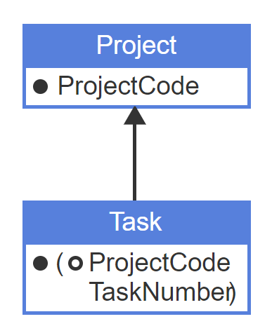
- Task depends on Project. ProjectCode is the primary key of Project.
- Task’s primary key includes Project’s primary key and an additional column, necessary for uniqueness.
- ProjectCode in Task table is also a foreign key.
If an entity depends on multiple entities, the primary key includes one foreign key for each master table. The primary key may include additional columns for uniqueness, depending on business rules.
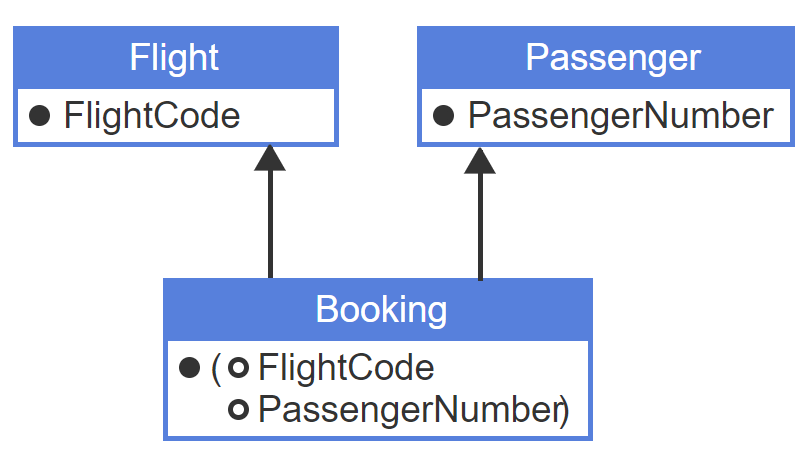
- Booking depends on Flight and Passenger.
- Booking’s primary key includes Flight and Passenger’s primary keys. In this case, no additional columns are necessary for uniqueness.
- FlightCode and PassengerNumber in Booking primary key are also foreign keys.
Database design
The implement entities step creates an initial table design and specifies primary keys. If no suitable primary key is available, an artificial key is specified. The design is augmented in subsequent steps, as relationships and attributes are implemented. The final SQL specification stabilizes as tables are reviewed for normal form.
Some decisions of the first step are affected by the database system. Ex: Some database systems have tools to automatically generate new artificial key values. A database designer might choose artificial primary keys more often when these tools are available.
4.7 Implementing relationships
Implementing many-one relationships
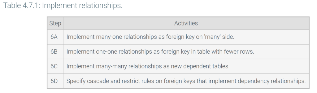
The ‘implement relationships’ step converts relationships into keys or tables, depending on relationship cardinality.
A many-one or one-many relationship becomes a foreign key:
- The foreign key goes in the table on the ‘many’ side of the relationship.
- The foreign key refers to the primary key on the ‘one’ side.
- The foreign key name is the primary key name with an optional prefix. The prefix is derived from the relationship name and clarifies the meaning of the foreign key.
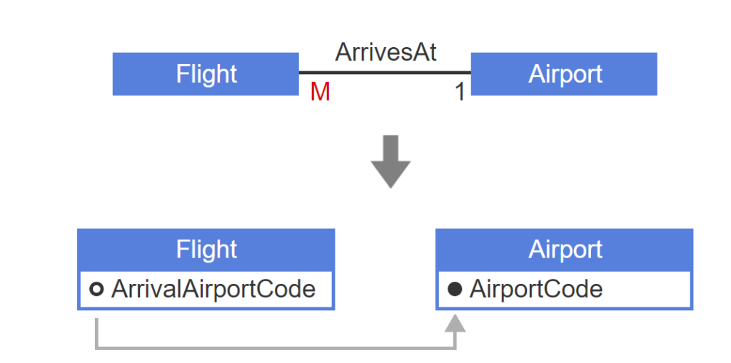
- Flight-ArrivesAt-Airport is a many-one relationship.
- The Airport entity becomes a table with primary key AirportCode.
- ArrivesAt becomes the foreign key ArrivalAirportCode on the ‘many’ side, referencing the primary key AirportCode on the ‘one’ side.
Implementing one-one relationships
A one-one relationship becomes a foreign key:
- The foreign key can go in the table on either side of the relationship. Usually, the foreign key is placed in the table with fewer rows, to minimize the number of NULL values.
- The foreign key refers to the primary key on the opposite side of the relationship.
- The foreign key name is the primary key name with an optional prefix. The prefix is derived from the relationship name and clarifies the meaning of the foreign key.
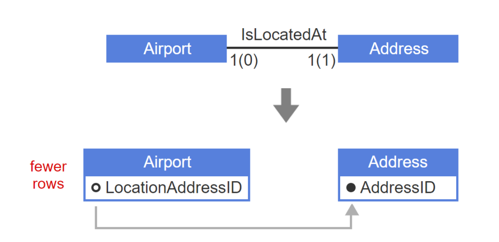
- Airport-IsLocatedAt-Address is a one-one relationship.
- The Address entity becomes a table with primary key AddressID.
- Address contains addresses of people as well as airports, so Address has more rows than Airport. The foreign key LocationAddressID goes in the table with fewer rows.
Implementing many-many relationships
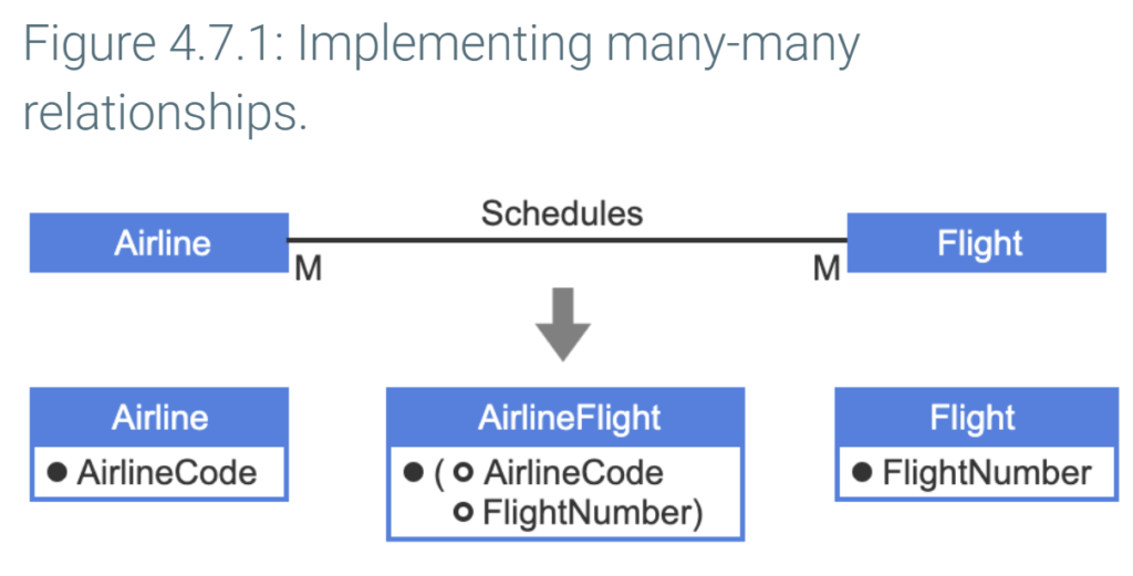
A many-many relationship becomes a new table:
- The new table contains two foreign keys, referring to the primary keys of the related tables.
- The primary key of the new table is the composite of the two foreign keys.
- The new table is dependent on the related tables, so primary key cascade and foreign key restrict rules are specified.
- The new table name consists of the related table names with an optional qualifier in between. The qualifier is derived from the relationship name and clarifies the meaning of the table.
In the figure below, the many-many relationship Airline-Schedules-Flight becomes the new table AirlineFlight. The primary keys from Airline and Flight become foreign keys in AirlineFlight, and the composite key (AirlineCode, FlightNumber) becomes AirlineFlight’s primary key
Database design
The ‘implement relationships’ step adds foreign keys to the initial table design. Each many-one and one-one relationship becomes a new foreign key. Each many-many relationship becomes a new dependent table containing two foreign keys.
Foreign keys that implement dependency relationships usually have the following referential integrity actions:
- Cascade on primary key update and delete
- Restrict on foreign key insert and update
Referential integrity actions are described elsewhere in this material.
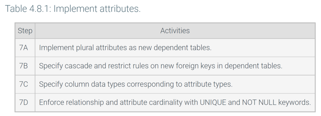
4.8 Implementing attributes
Implementing plural attributes
Attributes can be singular or plural:
- Each entity instance has at most one singular attribute instance.
- Each entity instance can have many plural attribute instances.
In the ‘implement entities’ step, entities become tables and attributes become columns. Singular attributes remain in the initial table, but plural attributes move to a new table:
- The new table contains the plural attribute and a foreign key referencing the initial table.
- The primary key of the new table is the composite of the plural attribute and the foreign key.
- The new table is dependent on the initial table, so primary key cascade and foreign key restrict rules are specified.
- The new table name consists of the initial table name followed by the attribute name.
If a plural attribute has a small, fixed maximum, the plural attribute can be implemented as multiple columns in the initial table. However, implementing plural attributes in a new table simplifies queries and is usually a better solution.
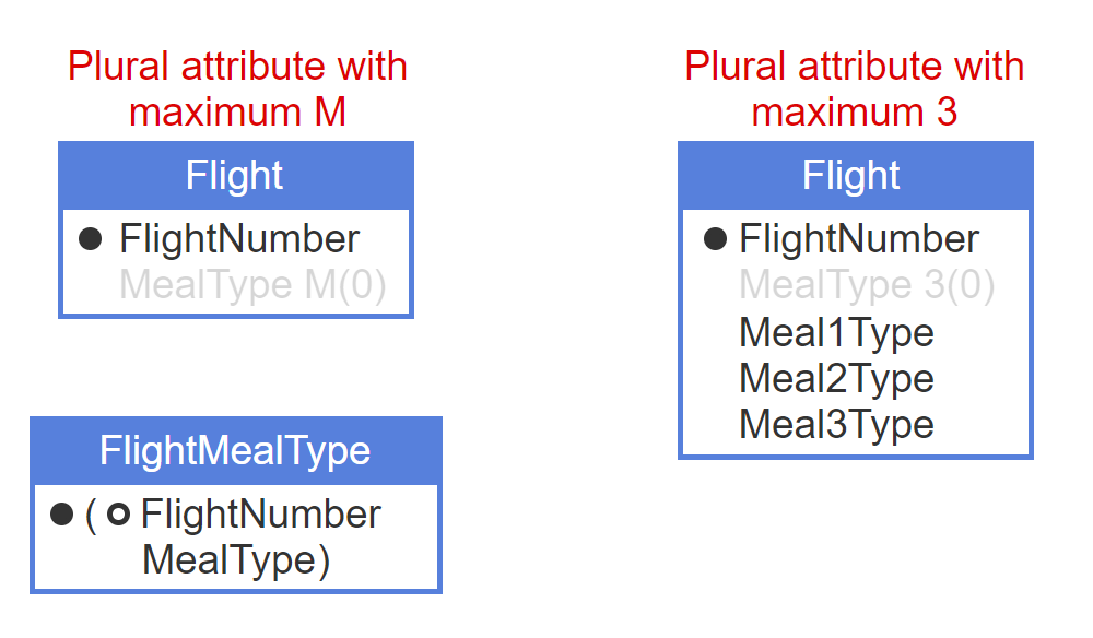
- Each flight offers several kinds of in-flight meals. MealType is a plural attribute of Flight.
- The plural attribute MealType moves to the new table FlightMealType. The foreign key FlightNumber references the initial table.
- The primary key of the new table is the composite of plural attribute MealType and foreign key FlightNumber.
- At most three meal types are offered on each flight, so MealType has a small, fixed maximum.
- Plural attributes with a small, fixed maximum can be implemented as multiple columns in the same table. MealType becomes three different columns.
Implementing attribute types
Each attribute has an attribute type included in the attribute name. During the discovery step, attribute types are selected from a list of standard attribute types in the glossary.
During logical design, an SQL data type is defined for each attribute type and documented in the glossary. When an attribute becomes a column, the attribute type determines the column data type. Ex: The attribute type Code has standard data type CHAR(4), so the FlightCode column is implemented with data type CHAR(4).
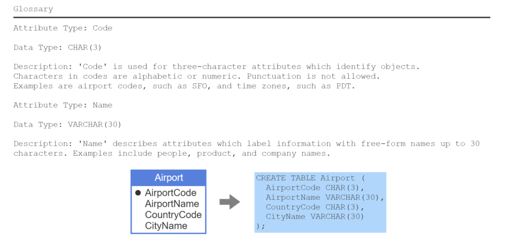
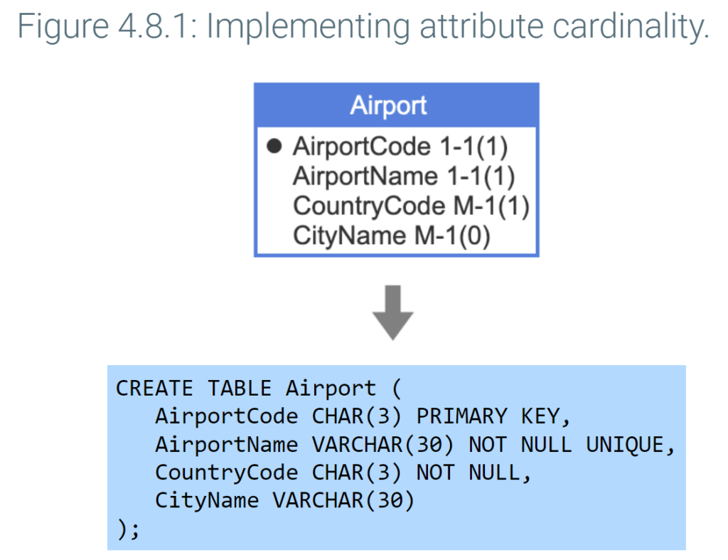
- The glossary specifies data types CHAR(3) and VARCHAR(30) for attributed types Code and Name, respectively.
- In the Airport entity, two attributes have attribute type Code and two have attribute type Name.
- In an SQL CREATE TABLE statement, attribute type Code is implemented as CHAR(3), and attribute type Name is implemented as VARCHAR(30).
Implementing attribute cardinality
Attributes can be unique, required, or optional:
- Each unique attribute instance describes at most one entity instance.
- Each entity instance has at least one required attribute instance.
- Each entity instance can have zero optional attribute instances.
Unique and required attributes are implemented with keywords following the column name in the CREATE TABLE statement:
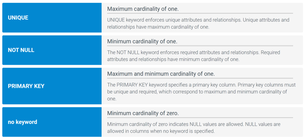
- UNIQUE is specified on columns derived from unique attributes.
- NOT NULL is specified on columns derived from required attributes.
- PRIMARY KEY is specified for primary key columns. The PRIMARY KEY keyword automatically enforces unique and required, so additional keywords NOT NULL and UNIQUE are unnecessary.
UNIQUE and NOT NULL are also specified on foreign key columns derived from unique and required relationships.
Optional attributes and relationships become columns with NULLs allowed and do not require special keywords.
The figure below shows the CREATE TABLE statement for the Airport entity. The AirportCode column is specified as the PRIMARY KEY. The AirportName attribute is required and unique, so NOT NULL and UNIQUE are specified for the column. The CountryCode attribute is required, so the CountryCode column uses NOT NULL. The CityName attribute is optional, so the CityName column allows NULL values.
Database design
The ‘implementing attributes’ step specifies columns, column rules, and data types. Plural attributes become new dependent tables. Unique and required cardinality is enforced with UNIQUE, NOT NULL, and PRIMARY KEY keywords.
After the ‘implementing attributes’ step, the database is completely specified in SQL as CREATE TABLE statements. The final step, ‘review tables for third normal form’, ensures that tables do not contain redundant data and fine-tunes the design if necessary.